Transistor Ignition circuit Schematic with explanation

Monday, July 18, 2011

Transistor Ignition circuit diagram

This transistor ignition circuit give your car to have better starting and smoother running, particularly at very high and very low RPM. Lower fuel consumption, less pollution, lower servicing costs. Drive economically, drive electronically. Only for petrol/gasoline engines. This circuit will reduce breaker point wear and provide cleaner spark.

Circuit diagram:

Transistor Ignition circuit Schematic

Wiring diagram with the vehicles:


Notes:
This circuit used for cars with negative ground 12V negative ground system, maximum ignition current of 4A and maximum switching speed 500KHz. Motorcycles, mowers, boats, etc can also use this circuit.

For 6V Negative ground system, change the following resistors:

  • R1, R2: 150 ohm / 1W
  • R3 : 68 ohm / 1/4W
  • R4 : 100 ohm / 1/4W
  • R5, R6, R7: 68 ohm / 1W

The kit of Electronic Transistor Ignition is available at electronickits.com, sell at $25.95.
Download the manual Transistor Ignition kit HERE

READ MORE - Transistor Ignition circuit Schematic with explanation

Car Horn circuit schematic with explanation

Car Horn circuit schematic with explanation

The following diagram is the schematic diagram fo Car Horn, you may try this circuit for your car modification… :)


Components List:

R1 = 68K
R2 = 2K2
R3 = 56K
R4 = 3K3
R5,R6 = 4K7
R7 = 10K Pot/trimpot
C1,C2 = 22nF
C3,C5 = 100nF
C4 = 1nF
C6 = 220µF/25V
IC1,IC2 = 7555 or TS555CN CMOS Timer ICs
IC3 = TDA7052
SPKR = 8 Ohm

Car Horn Circuit Description:

This car horn circuit reproduces the sound of contemporary vehicle horns. It had been mainly created for models and toys but, applying a high output energy audio amplifier IC, it could be implemented as well in further complicated projects.
Circuit operation

To receive a realistic automobile horn sound, two different tones mixed collectively are essential and the interval they’ll type ought to be a so known as minor third (in musical terms). This can be implemented by two 7555 CMos Timer ICs wired as astable multivibrators and generating a square wave of about 440Hz and 523Hz respectively. These frequencies ought to be quite precise, so the uncommon values necessary for your timing resistors are obtained by wiring two common worth resistors in series.

The square wave frequencies produced by IC1 (440Hz) and IC2 (523Hz) are mixed via R5 and R6 and shaped by C3, C4 and R7 in order to obtain a far more realistic tone. The resulting composite audio signal is ultimately sent for the audio power amplifier IC3 which, in turn, drives the loudspeaker. R7 needs to be adjusted to acquire a satisfactory output level.

Car Horn Circuit Notes:

  • The loudspeaker may be of any form and diameter. Certainly it need to withstand a energy of at the least 1 Watt if the TDA7052 Audio power amplifier IC is chosen.
  • The TDA7052 IC was used since it permits a minimum parts count and very excellent functionality. Wanting to make use of a distinct audio power amplifier IC, you are able to pick the much less effective but straightforward to find LM386 (see the Cuckoo-song Generator project).
  • In any case, try a great sized device, as a way to receive finest outcomes.
  • Needing a a lot more effective amplifier chip, it is possible to use the TDA2003 10W Car Radio Audio Amplifier IC or the TDA1516BQ 24W BTL Vehicle Radio Power Amplifier IC .

Source: RedCircuits


READ MORE - Car Horn circuit schematic with explanation

For Bicycles Rear Light After Glow circuit and explanation

This article is of interest only to readers whose bicycle lights are powered by a dynamo. The laws on bicycle lights in the United Kingdom are stricter than in other countries and a dynamo is, therefore, a rarity in this country. From the point of view of traffic safety it is advisable (in UK obligatory) for cyclists to have the rear lamp of their bicycle to light even when they are at standstill. In principle, it is not very difficult to modify the existing rear light with afterglow: all this needs is a large enough energy reservoir. Since the after-glow is required for short periods of time only, a battery is not required: a large value capacitor, say, 1 F, is quite sufficient.

As the diagram shows, in the present circuit, the normal rear light bulb is replaced by two series-connected bright LEDs, D2 and D3. These are clearly visible with a current of only 6 mA (compared with 50 mA of the bulb). The current is set with series resistor R1. The LEDs are shunted by the 1 F capacitor, C1. Since the working voltage of this component is only 5.5 V, it is, in spite of its high value, physically small. An effective regulator is needed to limit the dynamo voltage adequately. Normal regulators cannot be used here, since they do not work at low voltages. Moreover, such a device would discharge the capacitor when the cycle is at standstill.

Rear Light After Glow

Fortunately, there is a low-drop type that meets the present requirements nicely: the Type LP2950CZ5.0. Of course, the dynamo output voltage needs to be rectified before it can be applied to the regulator. In the present circuit, this is effected by half-wave rectifier D1 and buffer capacitor C2. Diode D1 is a Schottky type to keep any losses low – important for this application, because the ground connection via the bicycle frame usually causes some losses as well. The value of buffer capacitor has been chosen well above requirements to ensure that C1 is charged during the negative half cycles of the dynamo voltage.
READ MORE - For Bicycles Rear Light After Glow circuit and explanation

With Bass-Boost 10W Audio Amplifier High Quality, very simple design, No preamplifier required

High Quality, very simple design, No preamplifier required

This design is based on the 18 Watt Audio Amplifier, and was developed mainly to satisfy the requests of correspondents unable to locate the TLE2141C chip. It uses the widespread NE5532 Dual IC but, obviously, its power output will be comprised in the 9.5 - 11.5W range, as the supply rails cannot exceed ±18V. As amplifiers of this kind are frequently used to drive small loudspeaker cabinets, the bass frequency range is rather sacrificed. Therefore a bass-boost control was inserted in the feedback loop of the amplifier, in order to overcome this problem without quality losses. The bass lift curve can reach a maximum of +16.4dB @ 50Hz. In any case, even when the bass control is rotated fully counterclockwise, the amplifier frequency response shows a gentle raising curve: +0.8dB @ 400Hz, +4.7dB @ 100Hz and +6dB @ 50Hz (referred to 1KHz).

Amplifier with Bass-Boost:10W Bass Boost Amplifier Circuit Diagram
10W Bass Boost Amplifier Circuit Diagram
Parts:

P1_________________22K Log.Potentiometer (Dual-gang for stereo)
P2________________100K Log.Potentiometer (Dual-gang for stereo)
R1________________820R 1/4W Resistor
R2,R4,R8____________4K7 1/4W Resistors
R3________________500R 1/2W Trimmer Cermet
R5_________________82K 1/4W Resistor
R6,R7______________47K 1/4W Resistors
R9_________________10R 1/2W Resistor
R10__________________R22 4W Resistor (wirewound)
C1,C8_____________470nF 63V Polyester Capacitor
C2,C5_____________100µF 25V Electrolytic Capacitors
C3,C4_____________470µF 25V Electrolytic Capacitors
C6_________________47pF 63V Ceramic or Polystyrene Capacitor
C7_________________10nF 63V Polyester Capacitor
C9________________100nF 63V Polyester Capacitor
D1______________1N4148 75V 150mA Diode
IC1_____________NE5532 Low noise Dual Op-amp
Q1_______________BC547B 45V 100mA NPN Transistor
Q2_______________BC557B 45V 100mA PNP Transistor
Q3_______________TIP42A 60V 6A PNP Transistor
Q4_______________TIP41A 60V 6A NPN Transistor
J1__________________RCA audio input socket

Power Supply :
Power Supply Circuit DiagramPower supply parts:

R11_________________1K5 1/4W Resistor
C10,C11__________4700µF 25V Electrolytic Capacitors
D2________________100V 4A Diode bridge
D3________________5mm. Red LED
T1________________220V Primary, 12 + 12V Secondary 24-30VA Mains transformer
PL1_______________Male Mains plug
SW1_______________SPST Mains switch

Notes:
  • Can be directly connected to CD players, tuners and tape recorders.
  • Schematic shows left channel only, but C3, C4, IC1 and the power supply are common to both channels.
  • Numbers in parentheses show IC1 right channel pin connections.
  • A log type for P2 will ensure a more linear regulation of bass-boost.
  • Do not exceed 18 + 18V supply.
  • Q3 and Q4 must be mounted on heatsink.
  • D1 must be in thermal contact with Q1.
  • Quiescent current (best measured with an Avo-meter in series with Q3 Emitter) is not critical.
  • Set the volume control to the minimum and R3 to its minimum resistance.
  • Power-on the circuit and adjust R3 to read a current drawing of about 20 to 25mA.
  • Wait about 15 minutes, watch if the current is varying and readjust if necessary.
  • A correct grounding is very important to eliminate hum and ground loops. Connect to the same point the ground sides of J1, P1, C2, C3 &C4. Connect C9 to the output ground.
  • Then connect separately the input and output grounds to the power supply ground.
Technical data:
Output power:
10 Watt RMS into 8 Ohm (1KHz sinewave)
Sensitivity:
115 to 180mV input for 10W output (depending on P2 control position)
Frequency response:
See Comments above
Total harmonic distortion @ 1KHz:
0.1W 0.009% 1W 0.004% 10W 0.005%
Total harmonic distortion @ 100Hz:
0.1W 0.009% 1W 0.007% 10W 0.012%
Total harmonic distortion @ 10KHz:
0.1W 0.056% 1W 0.01% 10W 0.018%
Total harmonic distortion @ 100Hz and full boost:
1W 0.015% 10W 0.03%
Max. bass-boost referred to 1KHz:
400Hz = +5dB; 200Hz = +7.3dB; 100Hz = +12dB; 50Hz = +16.4dB; 30Hz = +13.3dB
Unconditionally stable on capacitive loads
READ MORE - With Bass-Boost 10W Audio Amplifier High Quality, very simple design, No preamplifier required

Playback Amplifier For Cassette Deck circuit schematic with explanation

For some time now, there have been a number of tape cassette decks available at low prices from mail order businesses and electronics retailers. Such decks do not contain any electronics, of course. It is not easy to build a recording amplifier and the fairly complex magnetic biasing circuits, but a playback amplifier is not too difficult as the present one shows. The stereo circuits in the diagram, in conjunction with a suitable deck, form a good-quality cassette player. The distortion and frequency range (up to 23 kHz) are up to good standards. Moreover, the circuit can be built on a small board for incorporation with the deck in a suitable enclosure. Both terminals of coupling capacitor C1 are at ground potential when the amplifier is switched on.

Circuit diagram:Cassette Deck Playback Amplifier Circuit Diagram
Cassette Deck Playback Amplifier Circuit Diagram

Because of the symmetrical ±12 V supply lines, the capacitor will not be charged. If a single supply is used, the initial surge when the capacitor is being charged causes a loud click in the loudspeaker and, worse, magnetizes the tape. The playback head provides an audio signal at a level of 200–500 mV. The two amplifiers raise this to line level, not linearly, but in accordance with the RIAA equalization characteristic for tape recorders. Broadly speaking, this characteristic divides the frequency range into three bands:
  • Up to 50 Hz, corresponding to a time constant of 3.18 ms, the signal is highly and linearly amplified.
  • Between 50 Hz and 1.326 kHz, corresponding to a time constant of 120 µs, for normal tape, or 2.274 kHz, corresponding to a time constant of 70 µs, for chromium dioxide tape, the signal is amplified at a steadily decreasing rate.
  • Above 1.326 kHz or 2.274 kHz, as the case may be, the signal is slightly and linearly amplified. This characteristic is determined entirely by A1 (A1’). To make the amplifier suitable for use with chromium dioxide tape, add a double-pole switch (for stereo) to connect a 2.2 kΩ resistor in parallel with R3 (R3’). The output of A1 (A1’) is applied to a passive high-pass rumble filter, C3-R5 (C3’-R5’) with a very low cut-off frequency of 7 Hz. The components of this filter have exactly the same value as the input filter, C1-R1 (C1’-R1’). The second stage, A2 (A2’) amplifies the signal ´100, that is, to line level (1V r.m.s.).
READ MORE - Playback Amplifier For Cassette Deck circuit schematic with explanation

Mini Guitar/Bass Amplifier circuit and explanation

Output power: 6W into 4 Ohm load, FET input stage - Passive Tone Control

Tiny, portable Guitar Amplifiers are useful for practice on the go and in bedroom/living room environment. Usually, they can be battery powered and feature a headphone output. This project is formed by an FET input circuitry, featuring a High/Low sensitivity switch, followed by a passive Tone Control circuit suitable to Guitar or Bass. After the Volume control, a 6W IC power amplifier follows, powered by a 12-14V dc external supply Adaptor or from batteries, and driving a 4 Ohm 10 or 13cm (4"/5") diameter car loudspeaker. Private listening by means of headphones is also possible.

Circuit diagram:Mini Guitar-Bass Amplifier Circuit Diagram
Parts:

P1______________1M Linear Potentiometer
P2____________100K Log Potentiometer
R1_____________68K 1/4W Resistor
R2____________470K 1/4W Resistor
R3______________2K7 1/4W Resistor
R4______________8K2 1/4W Resistor
R5____________680R 1/4W Resistor
R6____________220K 1/4W Resistor
R7_____________39R 1/4W Resistor
R8______________2R2 1/4W Resistor
R9____________220R 1/4W Resistor
R10_____________1R 1/4W Resistor
R11___________100R 1/2W Resistor
R12_____________1K5 1/4W Resistor
C1____________100pF 63V Polystyrene or Ceramic Capacitor
C2,C5,C9,C14__100nF 63V Polyester Capacitors
C3____________100µF 25V Electrolytic Capacitor
C4_____________47µF 25V Electrolytic Capacitor
C6______________4n7 63V Polyester Capacitor
C7____________470pF 63V Polystyrene or Ceramic Capacitor
C8______________2µ2 25V Electrolytic Capacitor
C10___________470µF 25V Electrolytic Capacitor
C11____________22nF 63V Polyester Capacitor
C12__________2200µF 25V Electrolytic Capacitor
C13__________1000µF 25V Electrolytic Capacitor
D1______________3mm red LED
Q1____________BF245 or 2N3819 General-purpose N-Channel FET
IC1_________TDA2003 10W Car Radio Audio Amplifier IC
SW1,SW2________SPST toggle or slide Switches
J1____________6.3mm Mono Jack socket
J2____________6.3mm Stereo Jack socket (switched)
J3_____________Mini DC Power Socket
SPKR__________4 Ohm Car Loudspeaker 100 or 130mm diameter

Notes:
  • Connect the output Plug of a 12 - 14V dc 500mA Power Supply Adaptor to J3
  • Please note that if the voltage supply will exceed 18V dc the IC will shut down automatically
Technical data:

Output power (1KHz sinewave):
6W RMS into 4 Ohm at 14.4V supply
Sensitivity:
50mV RMS input for full output
Frequency response:
25Hz to 20kHz -3dB with the cursor of P1 in center position
Total harmonic distortion:
0.05 - 4.5W RMS: 0.15% 6W RMS: 10%

Tone Control Frequency Response:
Mini Guitar/Bass Amplifier  circuit
READ MORE - Mini Guitar/Bass Amplifier circuit and explanation

Very Simple Bench Amplifier circuit and explanation

A small 325mW amplifier with a voltage gain of 200 that can be used as a bench amplifier, signal tracer or used to amplify the output from personal radios, etc. The circuit is based on the National Semiconductor LM386 amplifier. In the diagram above, the LM386 forms a complete non-inverting amplifier with voltage gain of x200. A datasheet in PDF format can be downloaded from the National Semiconductor website. The IC is available in an 8 pin DIL package and several versions are available; the LM386N-1 which has 325mW output into an 8 ohm load, the Lm386N-3 which has 700mW output and the LM386N-4 which offers 1000mW output. all versions work in this circuit. The gain of the Lm386 can be controlled by the capacitor across pins 1 and 8. With the 10u cap shown above, voltage gain is 200, omitting this capacitor and the gain of the amplifier is 20.

Finished project:
Circuit diagram:
Bench Amplifier Circuit Diagram

The IC works from 4 to 12Volts DC, 12Volt being the maximum recommended value. The internal input impedance of the amplifier is 50K, this is shunted with a 22k log potentiometer so input impedance in this circuit will be lower at about 15k. The input is DC coupled so care must be taken not to amplify any DC from the preceeding circuit, otherwise the loudspeaker may be damaged. A coupling capacitor may included in series with the 22k control to prevent this from happening.
READ MORE - Very Simple Bench Amplifier circuit and explanation

1W BTL Audio Amplifier circuit and explanation

The TDA8581(T) from Philips Semiconductors is a 1-watt Bridge Tied Load (BTL) audio power amplifier capable of delivering 1 watt output power into an 8-Wload at THD (total harmonic distortion) of 10% and using a 5V power supply. The schematic shown here combines the functional diagram of the TDA8551 with its typical application circuit. The gain of the amplifier can be set by the digital volume control input. At the highest volume setting, the gain is 20 dB. Using the MODE pin the device can be switched to one of three modes: standby (MODE level between Vp and Vp–0.5 V), muted (MODE level between 1 V and Vp–1.4 V) or normal (MODE level less than 0.5 V). The TDA8551 is protected by an internal thermal shutdown protection mechanism. The total voltage loss for both MOS transistors in the complementary output stage is less than 1 V.

Circuit diagram:1-Watt BTL audio amplifier
1 Watt BTL Audio Amplifier Circuit Diagram

Using a 5-V supply and an 8-W loudspeaker, an output power of 1 watt can be delivered. The volume control has an attenuation range of between 0 dB and 80 dB in 64 steps set by the 3-state level at the UP/DOWN pin: floating: volume remains unchanged; negative pulses: decrease volume; positive pulses: increase volume Each pulse at he Up/DOWN pin causes a change in gain of 80/64 = 1.25 dB (typical value). When the supply voltage is first connected, the attenuator is set to 40 dB (low volume), so the gain of the total amplifier is then –20 dB. Some positive pulses have to be applied to the UP/DOWN pin to achieve listening volume. The graph shows the THD as a function of output power. The maximum quiescent current consumption of the amplifier is specified at 10 mA, to which should be added the current resulting from the output offset voltage divided by the load impedance.
READ MORE - 1W BTL Audio Amplifier circuit and explanation

Condenser Mic Audio Amplifier circuit Schematic with explanation

The compact, low-cost condenser mic audio amplifier described here provides good-quality audio of 0.5 watts at 4.5 volts. It can be used as part of intercoms, walkie-talkies, low-power transmitters, and packet radio receivers. Transistors T1 and T2 form the mic preamplifier. Resistor R1 provides the necessary bias for the condenser mic while preset VR1 functions as gain control for varying its gain. In order to increase the audio power, the low-level audio output from the preamplifier stage is coupled via coupling capacitor C7 to the audio power amplifier built around BEL1895 IC.

Circuit diagram:
Condenser Mic Audio Amplifier circuit schematic

BEL1895 is a monolithic audio power amplifier IC designed specifically for sensitive AM radio applications that delivers 1 watt into 4 ohms at 6V power supply voltage. It exhibits low distortion and noise and operates over 3V-9V supply voltage, which makes it ideal for battery operation. A turn-on pop reduction circuit prevents thud when the power supply is switched on. Coupling capacitor C7 determines low-frequency response of the amplifier. Capacitor C9 acts as the ripple-rejection filter.

Capacitor C13 couples the output available at pin 1 to the loudspeaker. R15-C13 combination acts as the damping circuit for output oscillations. Capacitor C12 provides the boot strapping function. This circuit is suitable for low-power HAM radio transmitters to supply the necessary audio power for modulation. With simple modifications it can also be used in intercom circuits.
Author: D. Prabakaran - Copyright: Electronics For You Mag
READ MORE - Condenser Mic Audio Amplifier circuit Schematic with explanation

LM4906 Boomer Audio Power Amplifier circuit and epxlanation

The well-known LM386 is an excellent choice for many designs requiring a small audio power amplifier (1-watt) in a single chip. However, the LM386 requires quite a few external parts including some electrolytic capacitors, which unfortunately add volume and cost to the circuit. National Semiconductor recently introduced its Boomer® audio integrated circuits which were designed specifically to provide high quality audio while requiring a minimum amount of external components (in surface mount packaging only). The LM4906 is capable of delivering 1 watt of continuous average power to an 8-ohm load with less than 1% distortion (THD+N) from a +5 V power supply. The chip happily works with an external PSRR (Power Supply Rejection Ratio) bypass capacitor of just 1 µF minimum.


In addition, no output coupling capacitors or bootstrap capacitors are required which makes the LM4906 ideally suited for cellphone and other low voltage portable applications. The LM4906 features a low-power consumption shutdown mode (the part is enabled by pulling the SD pin high). Additionally, an internal thermal shutdown protection mechanism is provided. The LM4906 also has an internal selectable gain of either 6 dB or 12 dB. A bridge amplifier design has a few distinct advantages over the single-ended configuration, as it provides differential drive to the load, thus doubling output swing for a specified supply voltage. Four times the output power is possible as compared to a single-ended amplifier under the same conditions (particularly when considering the low supply voltage of 5 to 6 volts).

Circuit diagram:
LM4906 Boomer Audio Power Amplifier circuit schematic
Boomer Audio Power Amplifier Circuit Diagram

When pushed for output power, the small SMD case has to be assisted in keeping a cool head. By adding copper foil, the thermal resistance of the application can be reduced from the free air value, resulting in higher PDMAX values without thermal shutdown protection circuitry being activated. Additional copper foil can be added to any of the leads connected to the LM4906. It is especially effective when connected to VDD, GND, and the output pins. A bridge configuration, such as the one used in LM4906, also creates a second advantage over single-ended amplifiers. Since the differential outputs, Vo1 and Vo2, are biased at half-supply, no net DC voltage exists across the load.

This eliminates the need for an output coupling capacitor which is required in a single supply, single-ended amplifier configuration. Large input capacitors are both expensive and space hungry for portable designs. Clearly, a certain sized capacitor is needed to couple in low frequencies without severe attenuation. But in many cases the speakers used in portable systems, whether internal or external, have little ability to reproduce signals below 100 Hz to 150 Hz. Thus, using a large input capacitor may not increase actual system performance. Also, by minimizing the capacitor size based on necessary low frequency response, turn-on pops can be minimized.
READ MORE - LM4906 Boomer Audio Power Amplifier circuit and epxlanation

60 Watt Guitar Amplifier circuit and explanation

Bass, Treble, Harmonic modifier and Brightness controls
Output power: 40W into 8 Ohm and 60W into 4 Ohm loads

This design adopts a well established circuit topology for the power amplifier, using a single-rail supply of about 60V and capacitor-coupling for the speaker(s). The advantages for a guitar amplifier are the very simple circuitry, even for comparatively high power outputs, and a certain built-in degree of loudspeaker protection, due to capacitor C8, preventing the voltage supply to be conveyed into loudspeakers in case of output transistors' failure. The preamp is powered by the same 60V rails as the power amplifier, allowing to implement a two-transistors gain-block capable of delivering about 20V RMS output. This provides a very high input overload capability.

Amplifier circuit diagram:
60 Watt Guitar Amplifier circuit schematic
60 Watt Guitar Amplifier Circuit Diagram
Amplifier parts:

R1__________________6K8 1W Resistor
R2,R4_____________470R 1/4W Resistors
R3__________________2K 1/2W Trimmer Cermet
R5,R6_______________4K7 1/2W Resistors
R7________________220R 1/2W Resistor
R8__________________2K2 1/2W Resistor
R9_________________50K 1/2W Trimmer Cermet
R10________________68K 1/4W Resistor
R11,R12______________R47 4W Wirewound Resistors
C1,C2,C4,C5________47µF 63V Electrolytic Capacitors
C3________________100µF 25V Electrolytic Capacitor
C6_________________33pF 63V Ceramic Capacitor
C7_______________1000µF 50V Electrolytic Capacitor
C8_______________2200µF 63V Electrolytic Capacitor (See Notes)
D1_________________LED Any type and color
D2________Diode bridge 200V 6A
Q1,Q2____________BD139 80V 1.5A NPN Transistors
Q3_____________MJ11016 120V 30A NPN Darlington Transistor (See Notes)
Q4_____________MJ11015 120V 30A PNP Darlington Transistor (See Notes)
SW1_______________SPST Mains switch
F1__________________4A Fuse with socket
T1________________220V Primary, 48-50V Secondary 75 to 150VA Mains transformer (See Notes)
PL1_______________Male Mains plug
SPKR______________One or more speakers wired in series or in parallel Total resulting impedance: 8 or 4 Ohm Minimum power handling: 75W


Preamplifier circuit diagram:
guitar preamplifier circuit schematic
Guitar Preamplifier Circuit Diagram
Preamplifier parts:

P1,P2______________10K Linear Potentiometers
P3_________________10K Log. Potentiometer
R1,R2______________68K 1/4W Resistors
R3________________680K 1/4W Resistor
R4________________220K 1/4W Resistor
R5_________________33K 1/4W Resistor
R6,R16______________2K2 1/4W Resistors
R7__________________5K6 1/4W Resistor
R8,R21____________330R 1/4W Resistors
R9_________________47K 1/4W Resistor
R10_______________470R 1/4W Resistor
R11_________________4K7 1/4W Resistor
R12,R20____________10K 1/4W Resistors
R13_______________100R 1/4W Resistor
R14,R15____________47R 1/4W Resistors
R17,R18,R19_______100K 1/4W Resistors
C1,C4,C5,C6________10µF 63V Electrolytic Capacitors
C2_________________47µF 63V Electrolytic Capacitor
C3_________________47pF 63V Ceramic Capacitor
C7_________________15nF 63V Polyester Capacitor
C8_________________22nF 63V Polyester Capacitor
C9________________470nF 63V Polyester Capacitor
C10,C11,C12________10µF 63V Electrolytic Capacitors
C13_______________220µF 63V Electrolytic Capacitor
D1,D2____________BAT46 100V 150mA Schottky-barrier Diodes (see Notes)
Q1,Q3____________BC546 65V 100mA NPN Transistors
Q2_______________BC556 65V 100mA PNP Transistor
J1,J2___________6.3mm. Mono Jack sockets
SW1,SW2___________SPST Switches

Sensitivity:
35mV input for 40W 8 Ohm output
42mV input for 60W 4 Ohm output
Frequency response:
50Hz to 20KHz -0.5dB; -1.5dB @ 40Hz; -3.5dB @ 30Hz
Total harmonic distortion @ 1KHz and 8 Ohm load:
Below 0.1% up to 10W; 0.2% @ 30W
Total harmonic distortion @ 10KHz and 8 Ohm load:
Below 0.15% up to 10W; 0.3% @ 30W
Total harmonic distortion @ 1KHz and 4 Ohm load:
Below 0.18% up to 10W; 0.4% @ 60W
Total harmonic distortion @ 10KHz and 4 Ohm load:
Below 0.3% up to 10W; 0.6% @ 60W
Treble control:
+9/-16dB @ 1KHz; +12/-24dB @ 10KHz
Brightness control:
+6.5dB @ 500Hz; +7dB @ 1KHz; +8.5dB @ 10KHz
Bass control:
-17.5dB @ 100Hz; -26dB @ 50Hz; -28dB @ 40Hz

Notes:
  • The value listed for C8 is the minimum suggested value. A 3300µF capacitor or two 2200µF capacitors wired in parallel would be a better choice.
  • The Darlington transistor types listed could be too oversized for such a design. You can substitute them with MJ11014 (Q3) and MJ11013 (Q4) or TIP142 (Q3) and TIP147 (Q4).
  • T1 transformer can be also a 24 + 24V or 25 + 25V type (i.e. 48V or 50V center tapped). Obviously, the center-tap must be left unconnected.
  • D1 and D2 can be any Schottky-barrier diode types. With these devices, the harmonic modifier operation will be hard. Using for D1 and D2 two common 1N4148 silicon diodes, the harmonic modifier operation will be softer.
  • In all cases where Darlington transistors are used as the output devices it is essential that the sensing transistor (Q2) should be in as close thermal contact with the output transistors as possible. Therefore a TO126-case transistor type was chosen for easy bolting on the heatsink, very close to the output pair.
  • R9 must be trimmed in order to measure about half the voltage supply across the positive lead of C7 and ground. A better setting can be done using an oscilloscope, in order to obtain a symmetrical clipping of the output wave form at maximum output power.
  • To set quiescent current, remove temporarily the Fuse F1 and insert the probes of an Avo-meter in the two leads of the fuse holder.
  • Set the volume control to the minimum and Trimmer R3 to its minimum resistance.
  • Power-on the circuit and adjust R3 to read a current drawing of about 30 to 35mA.
  • Wait about 15 minutes, watch if the current is varying and readjust if necessary.
Author: www.redcircuits.com
READ MORE - 60 Watt Guitar Amplifier circuit and explanation

20W 12V Compact High-Performance Stereo Amplifier

Amplifiers which run from 12V DC generally don’t put out much power and they are usually not hifi as well. But this little stereo amplifier ticks the power and low distortion boxes. With a 14.4V supply, it will deliver 20 watts per channel into 4-ohm loads at clipping while harmonic distortion at lower power levels is typically less than 0.03%.

This is an ideal project for anyone wanting a compact stereo amplifier that can run from a 12V battery. It could be just the ticket for buskers who want a small but gutsy amplifier which will run from an SLA battery or it could used anywhere that 12V DC is available – in cars, recreational vehicles, remote houses with 12V DC power or where ever.

12 Volt 20W Stereo Amplifier circuit schematic

Because it runs from DC, it will be an ideal beginner’s or schoolie’s project, with no 240VAC power supply to worry about. You can run it from a 12V battery or a DC plugpack. But while it may be compact and simple to build, there is no need to apologise for “just average” performance. In listening tests from a range of compact discs, we were very impressed with the sound quality.

Long-time readers might recall that we presented a similar 12V power amplifier design back in May 2001. It was a similar configuration to this one but it is now completely over-shadowed by the much lower distortion and greatly improved signal-to-noise ratio of this new design. In fact, let’s be honest: the previous unit is not a patch on this new design. It used two TDA1519A ICs which resulted in distortion figures above 1% virtually across the board and a signal-to-noise ratio of only -69dB unweighted.

20W Stereo Amplifier circuit schematic

However, by using the TDA­7377 power amplifier IC and making some other improvements, the THD (total harmonic distortion) of the new design is about 50 times better than the older unit (see performance graphs for details). The bottom line is that the THD under typical conditions is around just 0.03% or less. It is also able to deliver more output power due to the improved output transistors in the new power amplifier IC.

In addition, its idle power consumption is low – not much more than 1W. As a result, if you don’t push it too hard it will run cool and won’t drain the battery too quickly. And because the IC has self-protection circuitry, it’s just about indestructible. It will self-limit or shut down if it overheats and the outputs are deactivated if they are shorted.

Circuit diagram:
12V 20W Stereo Amplifier circuit schematic
20W Stereo Amplifier Circuit Diagram

With a 12V supply, the largest voltage swing a conventional solid-state power amplifier can generate is ±6V. This results in a meagre 4.5W RMS into 4O and 2.25W RMS into 8O, without considering losses in the output transistors. Even if the DC supply is around 14.4V (the maximum that can normally be expected from a 12V car battery), that only brings the power figures up to 6.48W and 3.24W for 4O and 8O loads respectively – still not really enough.

There are three common solutions to this problem. The first is to boost the supply voltage using a switchmode DC converter. This greatly increases the cost and complexity of the amplifier but it is one way of getting a lot of power from a 12V supply. However, we wanted to keep this project simple and that rules out this technique.

Parts layout:
PCB layout of compact 12V 20W Stereo Amplifier circuit schematic

There are variations on the boosting method, such as the class H architecture used in the TDA1562Q IC featured in the Portapal PA Amplifier (SILICON CHIP, February 2003). It is able to achieve 40W/channel but with >0.1% THD. In that case, the amplifier output itself provides the switching for a charge pump. The second method is to lower the speaker impedance. Some car speakers have an impedance as low as 2O, which allows twice as much power to be delivered at the same supply voltage. However, we don’t want to restrict this amplifier to 2O loudspeakers.
Author: Nicholas Vinen - Copyright: Silicon Chip
READ MORE - 20W 12V Compact High-Performance Stereo Amplifier

TDA1562Q 36 Watt Audio Power Amplifier circuit and explanation

36 Watt Audio Power Amplifier Circuit Using TDA1562Q

It's based on a Philips class-H audio amplifier IC and can deliver 36W RMS OR 70W music power, all from a 13.8V supply. Our new Mighty Midget Amplifier can really pack a punch - around 36W RMS continuous into a 4-ohm load when using a 13.8V supply. However, it's the 70W of output power that it can deliver during dynamic (music) signal conditions that really make you sit up and take notice.

Picture of 36 Watt Audio Power Amplifier Using TDA1562Q

As can be seen from the photos and the circuit diagram, the Mighty Midget uses just a handful of parts. It's built on a PC board that measures just 104mm x 39mm but while its size may be modest, these's nothing at all modest about its power output. And the noise and distortion figures are pretty good too.

Circuit diagram:

36 Watt Audio Power Amplifier Circuit Diagram

At the heart of the circuit is the TDA1562Q IC, described by Philips as a "monolithic integrated Bridge-Tied Load (BTL) class-H high-efficiency power amplifier". It comes in a 17-pin "DIL-bent-SIL" plastic package and is not only designed for use in car audio and portable PA work but for mains applications as well; eg, mini/midi audio components and TV sound.

Parts layout:

Parts Layout Of 36 Watt Audio Power Amplifier

PCB layout:

PCB Layout Of 36 Watt Audio Power Amplifier

Performance:

Output power:----------------------36W RMS into 4R
Music power:-----------------------70W into 4R
Frequency response:---------------1dB down at 28Hz and 55kHz
Input sensitivity:-------------------130mV RMS (for 36W into 4?)
Harmonic distortion:----------------typically 0.2% (see graphs)
Signal-to-noise ratio:----------------95dB unweighted (22Hz to 22kHz)
READ MORE - TDA1562Q 36 Watt Audio Power Amplifier circuit and explanation

latest Electro Harmonix Graphic Equalizer circuit schematic with explanation

Sunday, July 17, 2011

latest Electro Harmonix Graphic Equalizer circuit schematic with explanation
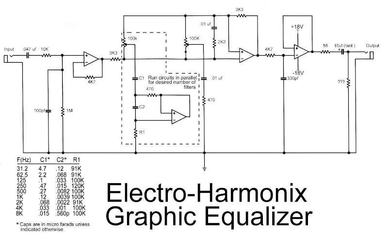
This is the diagram od electro-harmonix graphic equalizer. You can specify the number of channels according to your needs. You just need to parallel the components: C1, C2, R1, an om-amp, Potensiometer and a 470 ohm resistor. The frequency to be boost decided by C1, C2 and R1. See the diagram for the C1, C2 and R1 combination versus the frequency.

For the op-amp, you can use op-amp IC TRX6221, NE5532 or LM833. Use regulated power supply and high quality components to obtain the quality audio output.

READ MORE - latest Electro Harmonix Graphic Equalizer circuit schematic with explanation

Gibson RD Artist Guitar circuit schematic with explanation


The following diagram is the schematic of Gibson RD Artist bass guitar

Circuit Notes:

  1. Both compression and expansion effects are determined by the lead pickup output only.
  2. I and O in the design diagram refer to inner and outer connections for the specific plug / jack.
  3. P and J in the design diagram refer to plugs and jacks respectively.
  4. The two green wires connecting to the P1- (5,6) are signal grounds. P1-8 being used for plug priority sensing.

Gibson RD Artist guitar schematic diagram designed by Fabian P Hartery

Download the schematic in PDF file:
» Download Link

READ MORE - Gibson RD Artist Guitar circuit schematic with explanation

Latest Sound Effects Generator (8 different sound effects) circuit schematic with explanation

Sound Effects Generator (8 different sound effects) circuit diagram

All sounds in this circuit are generated by HT2884. There are 8 different sound effect can be produced that are 2 lazer guns, 1 dual tone horn sound, 2 bomb sounds, 2 machine gun sounds and a rifle shot sound.

Note:
Power is a 3 Volt battery, but the IC will work with any voltage between 2.5 and 5 Volts. Switch S1 is the on / off switch. The output at pin 10 is amplified and drives a small 8 ohm loudspeaker. Pressing S3 once will generate all the sounds, one after another. S2 can be used to produce a single sound effect, next depression gives the next sound effect. Standby current is about 1 uA at 3 Volt, so battery life is very economical.

READ MORE - Latest Sound Effects Generator (8 different sound effects) circuit schematic with explanation

latest Door Knob Touch Alarm circuit schematic with explanation

Door Knob Touch Alarm circuit diagram

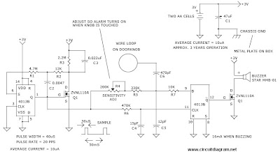
This is door knob touch alarm for your home security purpose. The alarm will be activated when someone touch the metal door knod. This circuit won’t work on full metal door.


Download the schematic drawing

READ MORE - latest Door Knob Touch Alarm circuit schematic with explanation

latest Simple Fire Alarm with Thermistor and NE555 circuit schematic with explanation

The following circuit is a simple fire alarm circuit based NE555 timer and use thermistor as a temperature detector. This sensor will activate the transistor when the temperature is in high value.

Simple Fire Alarm with Thermistor and NE555 circuit diagram

The thermistor will have a low resistance at high temperature, while at low temperature, the transistor resistance is high. This characteristic of thermitor is used to build the fire alarm.

The difference value of thermistor will decide the transistor 1 and transistor 2 to switching on or off, while TI and T2 has function to drive the NE555 to generate audio frequency. We can say that the thermistor’s condition (its sensing) will determine the alarm to be on or off.

Tags: 555, alarm circuit, circuit diagram of fire alarm, fire alarm, fire alarm circuit, fire alarm circuit diagram, fire alarm circuit using ic 555, fire alarm project, ne555, simple fire alarm, simple fire alarm circuit,

READ MORE - latest Simple Fire Alarm with Thermistor and NE555 circuit schematic with explanation

Latest British Police Car Siren circuit Schematic With explanation

British Police Car Siren circuit diagram

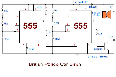
This is the sound generator which will simulate British police car siren. The circuit is built using 2 pieces of timer IC 555 to generate sound frequency.


How the circuit work:

The 555 on the right is wired as an alarm sound generator and the second 555 timer on the left is a 1 Hz astable multivibrator. The output of the left timer is to modulate the frequency of the right timer. This process will cause the right timers frequency to alternate between 440Hz and 550Hz at a 1 Hz cyclic rate. The transistor 2N3055 is used to amplify the sound signal to the loudspeaker. This circuit should be nice for newbie hobbysts.

Tags: british police siren, electronic siren, police car siren, police siren, police siren circuit diagram,

READ MORE - Latest British Police Car Siren circuit Schematic With explanation

latest Wailing Alarm Siren circuit Schematic with explanation

Wailing Alarm Siren circuit diagram

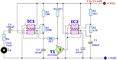
Here the wailing alarm circuit diagram:


Component parts List:

R1,R5___________ 4.7K
R2______________ 47K
R3______________ 10K
R4______________ 100K
Rx______________ *see text
C1,C4__________ 100uF/25V, electrolytic
C2,C3__________ 0.01uF (10nF), ceramic
T1_____________ 2N3702 (NTE159, TUP, etc.)
IC1,IC2________ LM/NE555, MC1455P, etc
LS_____________ Loudspeaker

*The Loudspeaker LS and the resistor marked “Rx” should be together 75 ohms. If you have a standard 8-ohm speaker then Rx is 67 ohms. The nearest value is 68 ohms. So for a 8 ohm loudspeaker Rx is 68 ohms. For a 4 ohm loudspeaker Rx is 71 ohms, for a 25 ohm loudspeaker Rx is 50 ohms, etc, etc.

circuit diagram by Tony van Roon,
source: http://www.sentex.ca/~mec1995/circ/wailing.htm


READ MORE - latest Wailing Alarm Siren circuit Schematic with explanation

Latest Car Alarm Simulator circuit Schematic with explanation

Car Alarm Simulator circuit diagram

This is a car alarm simulator which using the LED as a simulation output. This simple circuit can tell you whether your car is running or not by detecting the voltage difference when the car is on and off. This occurs because when your car is running the Alternator puts a out a voltage a little bit higher than when the car is off.

The circuit will be activated automatically when the engine is turned off.

How to run the circuit:
1. Connect the circuit to the car electrical system.
2. Adjust RV1 until the LED flashes when the engine is not running
3. Start the engine, the LED should turn off. If the LED still on, the andjust the RV1 slighty

This circuit actually is a kits, you can get the kits at http://www.electronickits.com/kit/complete/surv/vemk126.htm. But it is very possible to you to build your own car alarm simulator circuit.

Download the circuit manual HERE.

READ MORE - Latest Car Alarm Simulator circuit Schematic with explanation

Wireless Car Alarm circuit schematic with explanation

Saturday, July 16, 2011

Wireless Car Alarm circuit diagram

This circuit is a wireless car alarm system that is built using two circuit modules, namely modules of transmitter and receiver modules. This circuit works on FM radio waves. Car alarms can be used on vehicles that have a 6-12VDC power supply. You can use the voltage stabilizer if your car power supply is too large (eg 24V).

How the circuit works:
The mini VHF, FM transmitter is fitted in the vehicle at night when the car is parked in the car porch. The receiver unit is built with CXA1019. CXA1019 a single IC-based FM radio module which is freely available in the market, is kept inside.

Receiver is tuned to the transmitter’s frequency. When the transmitter is on and the signals are being received by FM radio receiver, no hissing noise is available at the output of receiver. Thus transistor T2 (BC548) does not conduct. This results in the relay driver transistor T3 getting its forward base bias via 10k resistor R5 and the relay gets energised.

When an intruder tries to drive the car and takes it a few metres away from the car porch, the radio link between the car (transmitter) and alarm (receiver) is broken. As a result FM radio module will generate hissing noise. Hissing AC signals are coupled to relay switching circuit via audio transformer. These AC signals are rectified and filtered by diode D1 and capacitor C8, and the resulting positive DC voltage provides a forward bias to transistor T2. Thus transistor T2 conducts, and it pulls the base of relay driver transistor T3 to ground level. The relay thus gets de-activated and the alarm connected via N/C contacts of relay is switched on.

If the intruder finds out about the wireless alarm (which already turned on) and disconnects the transmitter from battery, still remote alarm remains activated. It will not turn off the alarm because in the absence of signal, the receiver continues to produce hissing noise at its output. So the burglar alarm is fool-proof and highly reliable.

Circuit diagram source: www.electronic-circuits-diagrams.com

READ MORE - Wireless Car Alarm circuit schematic with explanation

Car Headlight Alarm circuit Schematic with explanation

This car headlight alarm circuit can be set for one or two functions:
First, to indicate that the head lights (or the side lights) should be switched off after switching off the ignition contact. With this circuit, there should be no dead battery due to headlights that were left on.
Second, to indicate that the head lights should be on once ignition contact is switched on.


Car Headlight Alarm Features:

  • Continuously repeated alarm tone for lights ON (may be disabled)
  • Repeated alarm tone for lights OUT
  • Only 3 wires are required for hook-up

Download the manual of Car Headlight Alarm here (you may buy the kit at electronickits.com with price of US$19.95)

READ MORE - Car Headlight Alarm circuit Schematic with explanation

Sensitive FM Transmitter circuit diagram

Sensitive FM Transmitter circuit diagram

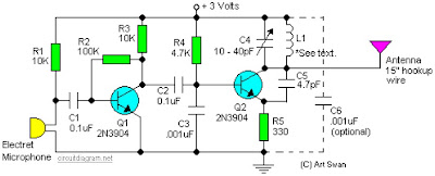
Simple and easy build of FM transmitter circuit. The circuit only require 2 transistors.


Circuit Notes:
Typically the default for the capacitors model is ceramic, preferably the npo 1% type or equivalent. However , generally almost nothing critical right here. Work with any capacitor you’ve laying arround, but DO NOT use any electrolytic or tantalum capacitors. Only in case you intend to apply this circuit outside the home you may need to use capacitores which have more temperature stability.

READ MORE - Sensitive FM Transmitter circuit diagram

Latest Touch Alarm System circuit schematic with explanation

Touch Alarm circuit is widely used for security, which is installed on the door. The advantages of this alarm is because the cost is cheap and difficult to detect by burglars / intruders. The following is an example of a touch of alarm circuit which is designed by Tony Van Roon.

Touch Alarm System circuit schematic

Components List:

R1 = 100K
R2 = 56K
R3 = 10M
R4 = 220K
P1 = 100K
D1 = 1N4004
T1 = 2N3904, or equivalent
U1 = 555 Timer*
C1 = 47μF/16V**
C2 = 33μF/16V**
Re1 = Relay***

Notes:

*The 555 can be a LM, NE, or MC(cmos) type, they’re all pin-compatible.

**C1/C2′s operating voltage should be elevated to 25V if you decide to go with a 12V energy source. Rule of thumb: the operating voltage of capacitors are at least double the supplied voltage, in other words, if the powersource is 9Volt, your capacitor(s) is a minimum of 18V. Transistor T1 could be any approximate substitute.

*** Use any suitable relay for the project and if you are not tight on area, use any size. I’ve develop this specific circuit to prevent students from fiddling using the security cameras in pc labs in the University I’m employed. I made certain the metal casing was not grounded. But as the schematic shows you can essentially hook it as much as any type of metal surface. I utilized a 12-vdc power adapter. Use any appropriate relay to handle your requirements. A ‘RESET’ switch (Usually Closed) can be added between the constructive and the ‘arrow-with-the-+’. The trigger (touch) wire is connected to pin 2 of the 555 and will trigger the relay, utilizing the body resistance, when touched. It is apparent that the ‘touching’ component has to be clean and can make good get in touch with with the trigger wire. This particular circuit may not be suitable for all applications. Just in case you wonder why pin 5 isn’t listed within the schematic diagram; it isn’t truly required. In certain noisy conditions a little ceramic capacitor is placed in between pin 5 and ground. It does no harm to add one or leave it out.

Extra note: For all those of you who didn’t discover, there is an approximate 5-second delay build-in prior to activation of the relay to avoid false triggering, or a ‘would-be’ thief, etc.

READ MORE - Latest Touch Alarm System circuit schematic with explanation

UM3561 based 4 sound effect generator circuit schematic with explanation

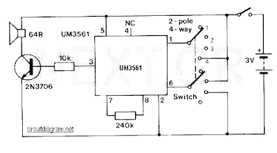
UM3561 based 4 sound effect generator circuit schematic with explanation

This is a really simple sound effect generator based single sound generator chip UM3561. The UM3561 will generate four kinds of sound effects. The basic operation is that the UM3561 will generate the sound signal, then the signal delivered to 2N3706 (as speaker driver) to be amplified so you can hear the sound from a speaker.

Each switch position will generate the follofing sound effect:

  • position 1 –> Police Siren
  • position 2 –> Fire Engine Siren
  • position 3 –> Ambulance Siren
  • position 4 –> Machine Gun

Download the UM3561 datasheet for sound effect generator circuit reference:
» Download Link

READ MORE - UM3561 based 4 sound effect generator circuit schematic with explanation

easy build motocycle alarm circuit Schematic with explanation

The following circuit is a simple, cheap and easy build motorcycle alarm. The circuit just required 2 transistors to drive the relay the the relay act as a switch to activate the buzzer.

easy build motocycle alarm circuit Schematic with explanation

Any number of normally-open switches may possibly be applied. Fit the mercury switches to ensure that they close when the steering is moved or when the bike is lifted off its side-stand or pushed forward off its centre-stand. Use micro-switches to secure removable panels as well as the lids of panniers and so on. Although at the very leastonce again – the alarm will reset. How lengthy it takes to switch off depends upon the characteristics of the actual parts you have utilized. You are able to adjust the time to suit your requirements by changing the value of C1 and/or R3.

easy build motocycle alarm component

The circuit board and switches need to be protected from the elements. Dampness or condensation will trigger malfunction. With out its terminal blocks – the board is small. Ideally, you need to attempt to locate a siren with sufficient spare space inside to accommodate it. Fit a 1-amp in-line fuse as close as achievable to the power source. This is Extremely Crucial. The fuse is there to secure the wiring – not the circuit board. Rather than utilizing a key-switch you’ll be able to use a hidden switch; or you could use the normally-closed contacts of a tiny relay. Wire the relay coil to ensure that it is energized whilst the ignition is on. Then each and every time you turn the ignition off – the alarm will set itself.

When it is not sounding – the circuit uses practically no present. This need to make it helpful in other circumstances. For instance, powered by dry batteries and using the relay and siren voltages to suit, it might be fitted inside a personal computer or anything else that is in danger of becoming picked up and carried away. The low standby electric current and automatic reset indicates that for this sort of application an external on/off switch might not be essential.

Easy build motorcycle alarm circuit source: www.zen22142.zen.co.uk

READ MORE - easy build motocycle alarm circuit Schematic with explanation

sound beeper circuit Schematic with explanation

sound beeper circuit Schematic

This is the circuit diagram of beeper sound. The circuit will generate the sound of a beeper which similar with the one in pagers. It produces a “beep-beep” sound. The work of this circuit is simple, the circuit applied the 555 timer oscillator which is turned ON and OFF periodically.
The first 555 IC (left IC) oscillates at about 1Hz. The second IC (gight IC) is turned ON and OFF by the first IC. The first IC will decide how fast the second IC is turned ON/OFF, while the second IC determines the tone frequency of the output. By adjusting the variable resistor VR1, the changeover rate can be vary. By adjusting VR2 the tone frequency can be altered.
Tags: 555 beeper, beeper alarm, beeper circuit, beeper diagram, beeper schematic, Beeper Sound schematic, electronic beeper sound,
READ MORE - sound beeper circuit Schematic with explanation

Low Voltage Alarm Circuit Schematic With explanation

Sunday, July 10, 2011

This low voltage circuit can be used to monitor batteries and other volatile sources of current for problems. The circuit sounds an alarm and lights an LED, but can be interfaced to any number of other circuits for many different uses.'Low Voltage Alarm Circuit

Parts

Part
Total Qty.
Description
Substitutions
R1, R321K 1/4W Resistor
R215K Pot
U11LM339 Op Amp IC
D111N5233B Zener Diode
D21LED
BZ11Piezo Buzzer
MISC1Board, wire, socket for IC

Notes

  1. The circuit will operate from 9V to 12V.
  2. Adjust R2 until the alarm goes off at the correct voltage.s
  3. \
Source : aaroncake.net/
READ MORE - Low Voltage Alarm Circuit Schematic With explanation

Digital Keypad Combination Lock Circuit Schematic with explanation

This simple circuit is the electronic version of the combination lock. Using the special purpose LS7220 digital lock IC, the circuit allows a 4 digit combination of your choice to activate a relay for a set period of time. This relay can then be used to trigger a lock solenoid, enable a starter button, open a motorized door, or many other tasks that require a momentary signal.Digital Keypad Combination Lock Circuit

Parts

Part
Total Qty.
Description
Substitutions
C111uF 25V Electrolytic Capacitor
C21220uF 25V Electrolytic Capacitor
R112.2K 1/4W Resistor
Q112N3904 NPN Transistor2N2222
D111N4148 Rectifier Diode1N4001-1N4007
K1112V SPDT RelayAny appropriate relay with 12V coil
U11LS7220 Digital Lock IC
S1-S1212SPST Momentary PushbuttonKeypad (see notes)
HD1112 Position Header

Notes

  1. To set the combination, wire the appropriate switches to U1 pins 3, 4, 5 and 6 using the header. For example if S1 was connected to pin 3, S2 to pin 4, S3 to pin 5 and S4 to pin 6, the combination would be 1,2,3,4. Now wire all other unused switches across the header to pin 2 of U1. In this way you can create any 4 digit combination you want. Pin 2 is the reset pin, so connecting all unused keys to it assures that the entire combination must be reentered if an incorrect key is pressed.
  2. When the appropriate combination is entered, the relay is activated for a period of time determined by C1. The 1uF capacitor specified in the parts list will result in an on-time of roughly 5 seconds. Increase the value of C1 to increase this time.
  3. An easy way to make a keypad is to buy 12 PC board mount pushbuttons and then etch a PC board so that the buttons are in 4 rows of 3, similar to a telephone keypad. Place this in a case and then use a label maker or transfer letters to add your numbers to the tops of the pushbuttons. You can also use a pre made keypad but keep in mind that you need a pad which provides an output for each key. Most pads available have the keys connected to provide a row and column signal when they are pressed.
Source: www.aaroncake.net
READ MORE - Digital Keypad Combination Lock Circuit Schematic with explanation

Air Flow Detector circuit Schematic with explanation

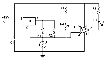
This simple circuit uses an incandescent lamp to detect airflow. With the filament exposed to air, a constant current source is used to slightly heat the filament. As it is heated, the resistance increases. As air flows over the filament it cools down, thus lowering it's resistance. A comparator is used to detect this difference and light an LED. With a few changes, the circuit can be connected to a meter or ADC to provide an estimation on the amount of air flow. Air Flow Detector circuit Schematic

Parts

Part
Total Qty.
Description
Substitutions
R11100 Ohm 1/4W Resistor
R21470 Ohm 1/4W Resistor
R3110k 1/4W Resistor
R41100K 1/4W Resistor
R511K 1/4W Resistor
C1147uF Electrolytic Capacitor
U1178L05 Voltage Regulator
U21LM339 Op Amp
L11#47 Incandescent lamp with glass removed (See "Notes")
D11LED
MISC1Board, Wire, Sockets for ICs, etc.

Notes

  1. The glass will have to be removed from L1 without breaking the filament. Wrap the glass in masking tape and it in a vise. Slowly crank down until the glass breaks, then remove the bulb and carefully peel back the tape. If the filament has broken, you will need another lamp.
READ MORE - Air Flow Detector circuit Schematic with explanation

AC Motor Speed Controller Circuit With explanation

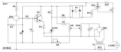
This AC motor speed controller can handle most universal type (brushed) AC motors and other loads up to about 250W. It works in much the same was a light dimmer circuit; by chopping part of the AC waveform off to effectively control voltage. Because of this functionality, the circuit will work for a wide variety of loads including incandescent light bulbs, heating elements, brushed AC motors and some transformers. The circuit tries to maintain a constant motor speed regardless of load so it is also ideal for power tools. Note that the circuit can only control brushed AC motors. Inductive motors require a variable frequency control. AC Motor Speed Controller Circuit

Parts

Part
Total Qty.
Description
Substitutions
R1127K 1W Resistor
R2110K 1/4W Resistor
R31100K 1/4W Resistor
R4133K 1/4W Resistor
R512.2K 1/4W Resistor
R611K 1/4W Resistor
R7160K Ohm 1/4W Resistor
R813K Linear Taper Trim Pot
R915K Linear Taper Pot
R1014.7K Linear Taper Trim Pot
R1113.3K 1/4W Resistor
R121100 Ohm 1/4W Resistor
R13147 Ohm 1W Resistor (See Notes)
C1, C320.1uF Ceramic Disc Capacitor
C21100uF 50V Electrolytic Capacitor
D116V Zener Diode
Q112N2222 NPN Transistor2N3904
SCR11ECG5400
TR11TRIAC (See Notes)
U11DIAC Opto-Isolator (See Notes)
BR1, BR225A 50V Bridge Rectifier
T11Transformer (See Notes)
MISC1PC Board, Case, Line Cord, Socket For U1, Heatsinks

Notes

  1. TR1 must be chosen to match the requirements of the load. Most generic TRIACs with ratings to support your load will work fine in this circuit. If you find a TRIAC that works well, feel free to leave a comment.
  2. U1 must be chosen to match the ratings of TR1. Most generic DIAC based opto-isolators will work fine. If you have success with a specific part, feel free to leave a comment.
  3. T1 is any small transformer with a 1:10 turns ratio. The circuit is designed to run on 120V so a 120V to 12V transformer will work. Alternately, you can wind T1 on a transformer core using a primary of 25 turns, a secondary of 200 turns, and 26 gauge magnet wire.
  4. R9 is used to adjust motor speed. R10 is a trim pot used to fine tune the governing action of the circuit. R8 fine tunes the feedback circuit to adjust for proper voltage at the gate of SCR1. It should be adjusted to just past the minimum point at which the circuit begins to operate.
  5. R13 must be chosen to match the load. Generally, larger loads will require a smaller value.
  6. Since this circuit is not isolated from mains, it must be built in an insulated case.
Source: aaroncake.net
READ MORE - AC Motor Speed Controller Circuit With explanation


User Agreement and Disclaimer

Labels

Electronics

LINKS