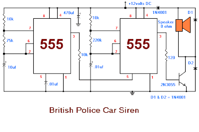
This is the sound generator which will simulate British police car siren. The circuit is built using 2 pieces of timer IC 555 to generate sound frequency.
How the circuit work:
The 555 on the right is wired as an alarm sound generator and the second 555 timer on the left is a 1 Hz astable multivibrator. The output of the left timer is to modulate the frequency of the right timer. This process will cause the right timers frequency to alternate between 440Hz and 550Hz at a 1 Hz cyclic rate. The transistor 2N3055 is used to amplify the sound signal to the loudspeaker. This circuit should be nice for newbie hobbysts.
Tags: british police siren, electronic siren, police car siren, police siren, police siren circuit diagram,

1 comments:
How to find the right 555 timer?
Post a Comment