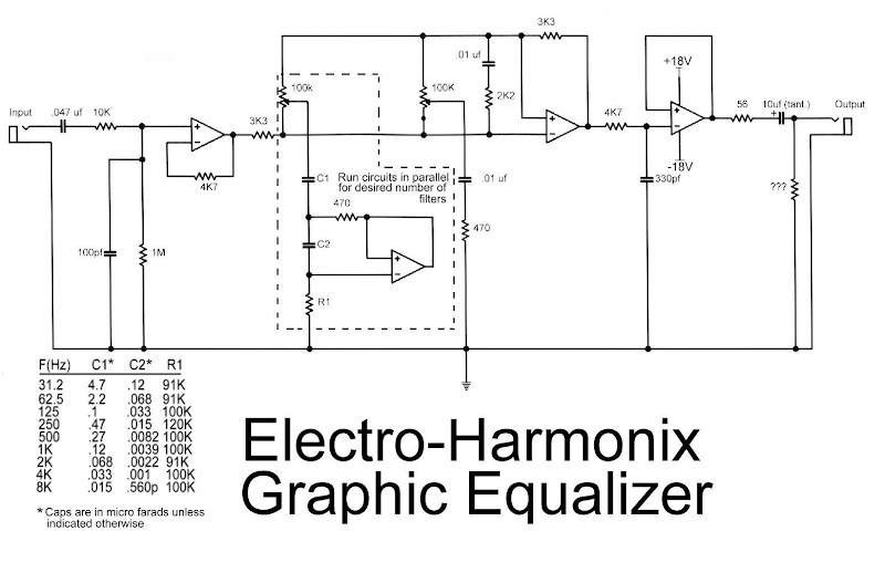
This is the diagram od electro-harmonix graphic equalizer. You can specify the number of channels according to your needs. You just need to parallel the components: C1, C2, R1, an om-amp, Potensiometer and a 470 ohm resistor. The frequency to be boost decided by C1, C2 and R1. See the diagram for the C1, C2 and R1 combination versus the frequency.
For the op-amp, you can use op-amp IC TRX6221, NE5532 or LM833. Use regulated power supply and high quality components to obtain the quality audio output.
0 comments:
Post a Comment